Electronics Projects: 'Originals'
This page has 'original' electronics projects I'm working on: none of them are actually completed, and there's no guarantee they will be. I'm really trying to, though!
Picogirl - RP2040 Gameboy DMG Emulator
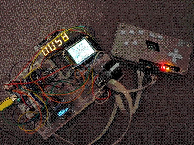
A Gameboy emulator that runs on RP2040 (Raspberry Pi Pico) is nothing new, and this is very much an amateur attempt: if you're looking for a ready-to-go Gameboy emulator that runs well on the Pico, I would suggest deltabeard's excellent Peanut-GB, which I have looked at many times when I'm stuck on how to implement something. However, I wanted to write a Gameboy emulator with some limited constraints and interfacing with low-level hardware, so I'm having a go at it! This is Picogirl, an emulator for the original Gameboy DMG that runs on RP2040.
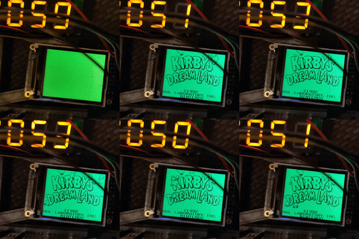
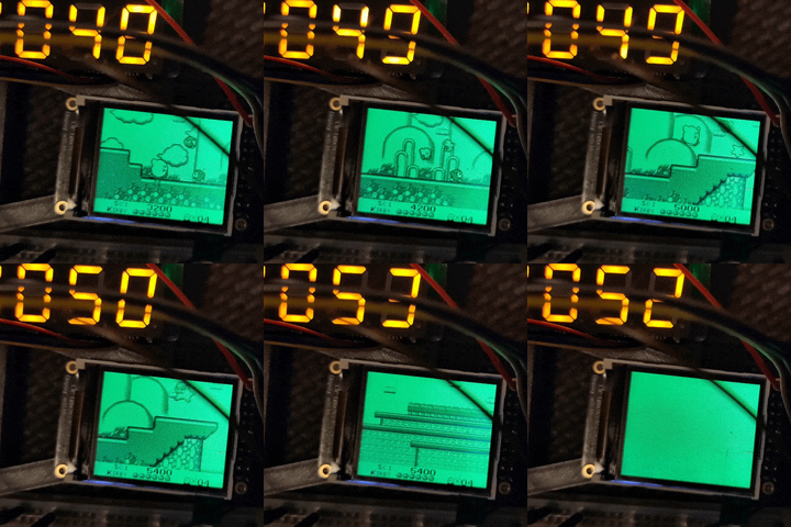
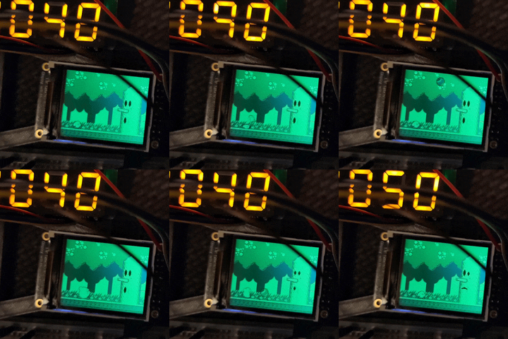
The overall structure of emulator/supporting hardware isn't too complex: the first RP2040 core handles CPU and PPU (Picture Processing Unit) emulation (using a cycle timing approach to keep everything in sync), while the second core just handles writing to the display over SPI. Input is provided via a keyswitch matrix (which is how the Gameboy's CPU is expecting to interpret input anyway) wired to the GPIO pins. APU (Audio Processing Unit) emulation is currently a bit hacky, for reasons I'll get into later, but this is mostly handled by the PWM blocks and sent out through a very very simple mixer into an off-the-shelf Adafruit amp.
At the moment, games have to be baked directly into the binary with a #include header file (yes, I'm writing this in C++) - game loading is on the to-do list, but it'll have to be copied to the QSPI flash onboard the microcontroller for speed. There's also some indicator LEDs on the 'gamepad', a 4-digit 7-segment display connected over I2C as a framerate counter, and a little OLED connected over I2C to print debug information (which is absolutely indispensable).
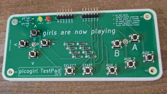
The gamepad was something I designed after I was actually getting games running and playing them to test the emulator: the original setup just had tiny buttons in the centre of a breadboard with diodes stretched between them, which was absolutely miserable to use as input. The design isn't complicated: it basically just puts the eight Gameboy buttons in a nice form factor on a single board, wires them up to the diodes, and puts the row/column pins on a header to connect to the rest of the Picogirl breadboard.
It also includes a 'debug header' which has ground, three direct-to-ground buttons, and a couple of LEDs. These 'aux buttons' can be programmed to do a bunch of things, but the main use for two of them is to scroll the screen up and down, since the most reasonable screen I could find is only 160x128 (vs. the Gameboy's actual 160x144 resolution). I'm planning to switch to a higher res screen at some point, but most of the other panels are either way smaller or larger in physical size, and would all require sizeable borders around the actual screen render area.
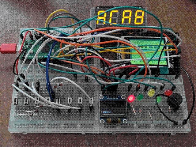
Audio emulation is currently... very hacky. The first three channels work by reading the values in the register and just turning on a PWM block at the correct frequency (although channel 1 does respect the frequency/period sweep, changing the PWM frequency accordingly). This means no volume adjustment, since that would require the Pico to micromanage the PWM blocks to generate a tone at the correct frequency, and it also means that channel 3 doesn't actually play any unique waveforms: the wave data registers are ignored entirely. Channel 4, being white noise, is bit-banged using a couple of pre-generated arrays of random bits (depending on what LFSR length is selected). It does work pretty well and music is extremely recognizable (not to mention that using the PWM blocks means the frequencies are independent of how fast the emulator's running), but it's pretty shoddy and I want to improve it. Bit-banging the white noise channel is also a significant performance hit.
The current best bet I have is writing an APU implementation using the PIO (Programmable Input/Output) blocks of RP2040, which should remove the burden from the main CPU entirely and allow for more accuracy. I don't have very many instructions to work with, though. For channel 4 specifically, I've put together a hardware LFSR that the Pico can drive for fast and very accurate white noise generation: more on that in the next section.
LFSR (Linear Feedback Shift Register)
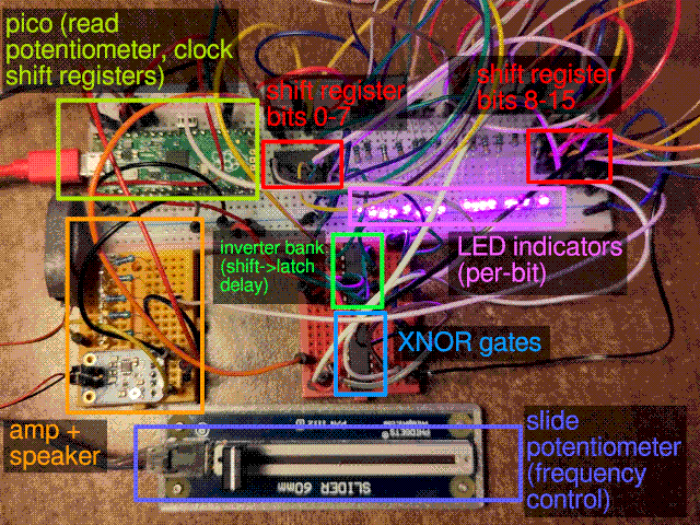
LFSRs have lots of theory behind them and many applications, which you can read about on their Wikipedia page. The basic idea is that by using the outputs of a shift register and some logic gates, you can use the current state of the shift register to feedback into the input. This will create a sequence that isn't actually random, but will result in a very long pseudorandom chain that doesn't require any 'computation' to generate (all the Pico is doing here is reading the potentiometer and generating and clock signal).
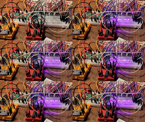
What I care about, however, is using them to make fucked up noises. You can't hear this one because I can't upload audio, but it sounds pretty neat. You can look at the pretty lights flashing though.
Picosynth (not the PICO-8 tool by Johan Peitz I should really think of another name)
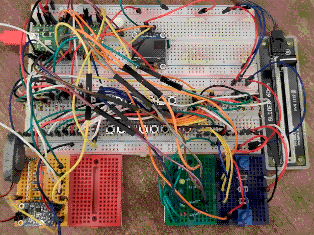
Picosynth is meant to be an all-in-one Pi Pico-based synthesizer - again, that's not anything new, but I wanted to try making one myself so I am. The original concept was to use the main CPU cores to bit-bang wave data with high frequency PWM controlling the 'volume', but much like in Picogirl, that's just too much work for the CPU to dedicate itself to (once more than a couple of tones are playing, the pitch starts to fall as the Pico can't keep up anymore). I still want to do it and will probably end up using a similar solution to the PIO APU I'm planning for Picogirl (in fact, I'm probably going to convert my LFSR prototype into a general PIO synthesizer testbed), but for now it's on the backburner.
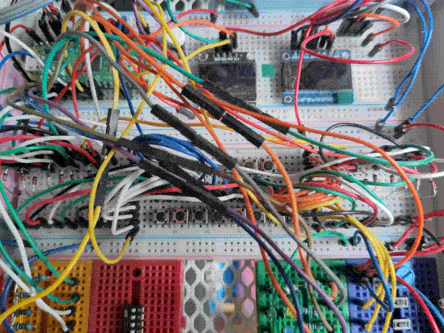
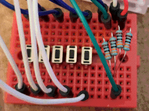
Slimetime - Hybrid Virtual Slime Mold Pet
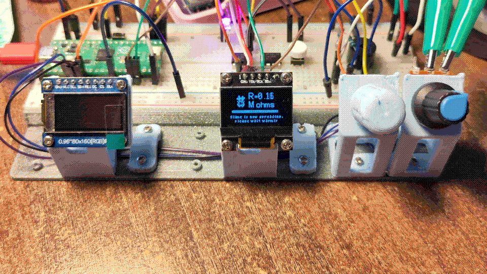
So this is a project that's extremely extremely early on, to the point where I don't really have much to write about it. The basic idea is that it's a virtual pet, like a Tamagotchi, but instead of taking care of the pet via the software on the device you take care of an actual slime mold growing in a little removable channel. Since the slime mold can conduct electricity, keeping it healthy enables games and features on the virtual pet device. I'd been thinking of making a virtual pet for awhile, and this solves several issues I was having with the concept: having the pet be a real slime mold reduces the amount of attention it needs (a Tamagotchi needs to be watched basically constantly for 'good care'), adds a real incentive to continue to provide care after the novelty wears off, and sidesteps a lot of the ideological problems that pop up with a Tamagotchi around gender, eating habits & body weight, etc.
The project is inspired and based on the work by Jasmine Lu and Pedro Lopes in their work Integrating Living Organisms in Devices to Implement Care-based Interactions, which explicitly mentions virtual pets as a touchstone and asks the participants of the study about them. It's really good and you should read it (there's an open access copy available here, last I checked). However, I have to come clean: I only found out about it because a certain extract gained traction on Tumblr, and it gained traction because... well I'll just quote it here.
While she was sick, P5's partner helped take care of her as well as helped to take care of her device. P5 recounts, "I was taking care of the slime and feeding it oats and stuff, my partner was also feeding me oatmeal because I was sick and so she was like you're my little slime and I was like yeah, I am (...) then she started calling me her slime because I mean me and the slime, like, we were eating the same stuff, (...) we were both being fed and watered".
Thank you to participant P5 and her partner for their contribution to the dissemination of research.
The first thing I did was getting a good rendering baseline for the little OLED display I'm using: since I eventually want this to be a virtual pet with little sprites and games and a decent UI, having a way to draw sprites with 'transparency' in arbitrary locations on the screen is actually pretty important (and something the example SSD1306 driver I've been adapting couldn't do "out of the box"). Eventually I want to expand this into a general rendering layer that can plug into different types of displays (an OLED isn't really a good display technology for something that's going to be on all the time), but for now this is extremely good enough.
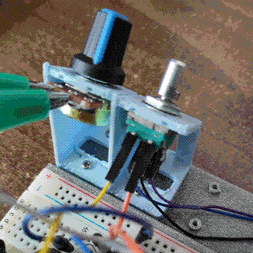
While resistance measurement and op-amp shenanigans were next, along the way I added this little modular rack system to put components on. It was originally just intended for stuff that couldn't go on a breadboard, like the potentiometer and encoder, but I also expanded it to stuff like displays that are perfectly breadboard-able but take up way more room than their number of pins.